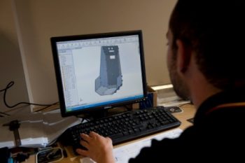
CAD stands for Computer Aided Design and combined with CAM (Computer Aided Manufacturing) it allows designers to use computer systems to first design a product and then to control the manufacturing processes. In other words once an engineer has created a design using CAD, the design itself can then control the machines that construct the component.
Thompson Precision have always been early adopters of technology as we believe that this allows us to offer the greatest level of technical expertise to our clients. Precision engineering in particular has benefitted enormously from digitisation. The advent of CAD and CAM systems has allowed for huge leaps forward in precision engineering, particularly combined with the latest CNC machining equipment.
The 3D CAD software allows us to create an image from the client’s basic sketches. Specifications for the drawings’ width, length and mass are entered into the computer programme and the software then creates a three dimensional image based upon this, allowing the drawing to now be viewed from any angle.
A physical prototype can also then be created by sending the 3D CAD image to the CNC machines. What makes the CAD software so useful to precision engineering is that the 3D image can be tweaked as many times as is necessary in order to create a new prototype. As precision engineering allows for incredibly accurate detail in a component, it’s important that the software can plot this to the tiniest detail and that is what CAD allows manufacturers to do. It creates an accurate computer image to instruct the machines to make the prototype exactly to the right measurements and specification.
How is CAD Used in Precision Engineering?
Here are some examples where CAD is useful in precision engineering:
- To create very detailed new products to incredibly precise measurements.
- To increase tiny pieces of machinery which require a perfect finish or precision cuts into the surface.
- To reproduce old components which are no longer being made, e.g. to reconstruct very old machinery or to create the parts needed to fix old but still useful engines for which replacement parts are no longer available.
- To design and create small computer parts to the level of extreme detail which is required.
The above can be useful in a variety of applications, including electronic, mechanical and automotive, allowing for the design and creation of precision engineered prototypes in a wide diversity of industries.
Using CAD software also allows engineers to illustrate to clients exactly how a finished product will behave, which is vital when dealing with the complex and intricate components usually manufactured using precision engineering. This results in fewer mistakes in initial prototypes, allowing the mistakes to be corrected in the software before anything is actually manufactured. Where multiple detailed parts need to fit perfectly with one another in order to correctly together, this can also be viewed on screen before going to the expense of creating each of the parts in physical form.
In short, by combining CAD software with CAM systems and precision engineering machinery, almost anything becomes possible when it comes to manufacturing detailed and precise components and prototypes with the minimum of mistakes.


