The Solution

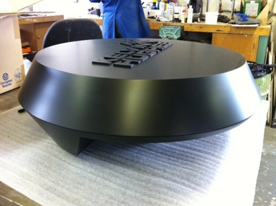
The client had a 2D drawing of the radar radome that they wanted a model of with the required dimensions. Therefore before any machining could start the 2D drawing had to be turned into a 3D CAD model. With the machining method decided as being CNC milling the CAD data could then be specifically designed for this method of manufacture. The client requested the model be split in two parts; a bottom and a top half. This information was then passed onto our design team where one of our design engineers produced a 3D CAD model of the radome. The two halves of the model were designed precisely to the outside shape the client requested, this was done in our 3D CAD software Solid Works. The client also wanted their company logo embossed onto the top of the model which was added to the 3D CAD model. The inside of the radome had to be shelled out to allow for a specific sized circuit board and several electronic components, which all had to be securely held in place and easily fit within the model. With the circuit board and components sent to us by the client our design engineer could fit these within the model.
3D CAD Finished Models
The finished 3D CAD models were then given to our CNC engineers where they were imported into our CAM software Power Mill, with each part designed with ease of manufacture in mind.The model was made from a solid block of high density model board (Ureol). Both parts were machined using a 3 axis CNC machining centre with each being inspected once finished to make sure it meets our clients high standards. The parts were then passed onto our model makers where the parts were then painted and hand finished.


